
Introducing the robot
In this articles we are going to introduce the Blue Seal robot.
My plan was to build a compact mobile robot with variety of sensors to ensure robot's adaptability for future unknown tasks. For that purpose I decided to use the Raspberry Pi computer, which I will introduce a little more in the subsection Choosing the right board.
Since the Raspberry Pi computer requires relatively large wattage, I used six AA chargeable batteries of large capacity (c. 2700mAh each). The stability of the energy source is also of our concern, because the computer requires strictly defined voltage but drains mutable current (c. 700-1000mA mainly due to active devices connected to the USB ports and the camera module).

The energy source must be stable, even if the drain from the batteries increases and decreases rapidly in a very short time as the stepper motors get engaged and disengaged (c. 1000mA each at work).
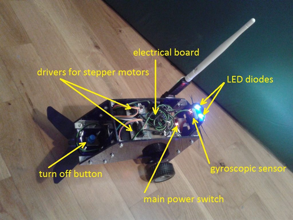
Other problem is imposed by output limits on the GPIO ports of the Raspberry Pi (c. 1-3mA each) ensuring that the computer board does not burn-out. The limits are not enforced and one can easily break the computer by crossing them. Unfortunately, these limits are to low that one cannot even use them for direct and safe supply for a single LED diode. For that purpose I design the electrical board also with capability to amplify the current coming out from the GPIO ports to reasonable values. We will introduce the electrical board in subsection Energy source.
The greatest electric vampires are the two stepper motors, which are draining large currents while working. To overcome their energetic demands we engage them only when we want to change position of the robot. We can drive the motors thanks to driver boards, which are capable of transforming the low current output of the GPIO ports to large values of 1000mA. We will introduce the stepper motors in subsection Motors and Wi-Fi along with the Wi-Fi adapter.

I also wanted to have control of the robot and be able to turn it on and off without having to connect to its Wi-Fi network. For that purpose I placed a turn-off button on the tail of the robot. Pressing the button sends a signal to Raspberry Pi computer, which executes switch off command and shuts down.
There is a rubber wheel attached directly to rotor's axis of every stepper motor. I have used no additional gearing in order to save place, mass and make the construction as easy as possible. For time reasons I had to settle down with an furniture wheel as the last supporting point. Initially, I though of replacing it with an all-directional ball caster, but I got used to the "Number 5" style given by the furniture chair and wont probably never change it, even dough the furniture wheel makes the trajectories of the robot slightly irregular with high difficulty of prediction.
An ultrasonic distance sensor is built-in in the front face off the robot. Originally, I intended to use the sensor to obtain the exact position of the robot. This ambitious intention met the reality process and time management of the Linux based Raspberry Pi computer, which prohibit exact measurements of the distance. Nevertheless, the sensor can be used at least to approximate the distance from distant objects as a wall.
The orientation of the robot can be obtained from a combined 3-axis gyroscopic and 3-axis accelerator sensor connected through I²C bus (denoted as gyroscopic sensor in the pictures). This sensor works well and can be used to detect changes in orientation of the robot. For absolute orientation of the robot we can connect a magnetometer directly to the gyroscopic sensor via I²C bus additional ports. We will introduce the sensors in subsection Sensors.
And now, last but not least, we would like to comment on the robot's case shaped in form of a seal. I left this part intentionally for the end, because the case was also the last part I have designed. Once I had finished all hardware parts and tried out their functionality, I faced the full dimension of the robot's inner body. It was clear that the robot's inner parts needed quite a large case capable of supporting quite a large mass of the batteries and electrical circuits.
I decided to shape the robot in a form of a seal, because the concept of two driven wheels and one additional supporting wheel reminded me of these dogs of the seas. Besides of that, I love animals. We will learn more about the seal-case in subsection Body.
We have introduced the Blue Seal Robot and we already are able to understand the robot's possibilities given by its components. Further details on the components, sensors or case an be found in subsections of this section. In following sections we will learn how to set up the robot and make it operational.
Share this page with friends via